Applicable version(s):
Latest stable release & Development version
by Carlos Remuzzi, BEng Biomedical Engineering, Freelance Developer, London UK
How vmtkMeshGenerator works
The mesh generator for vmtk works by performing two fundamental steps, Surface Remeshing and Volume Meshing.
Surface remeshing
Surface remeshing is performed under the assumption that the surface requires improvement before being used for CFD. In the surface remeshing step, the surface triangle edges are resized according to two alternative methods decided by the user:
- a target edge length is uniformly assigned to the whole surface.
- a scalar sizing function is adopted to resize the triangles. The scalar sizing function can be of any type, usually the distance of the surface points from the centerline will be adopted.
Volume meshing
After the surface has been remeshed the volume is filled with a combination of tetrahedral and prismatic elements. This task relies on algorithms based on Tetgen. The parameter -volumeelementfactor is used to control the size of the tetrahedral mesh and it represents a proportionality constant between the local surface edge length and the element volume. There’s is another option involved in Volume meshing, it’s the Boundary Layer. By activating it we can heighten the density of the mesh near the wall. We can adda a boundary layer by using the -boundarylayer option . The thickness of this layer can be specified through the -thicknessfactor parameter.

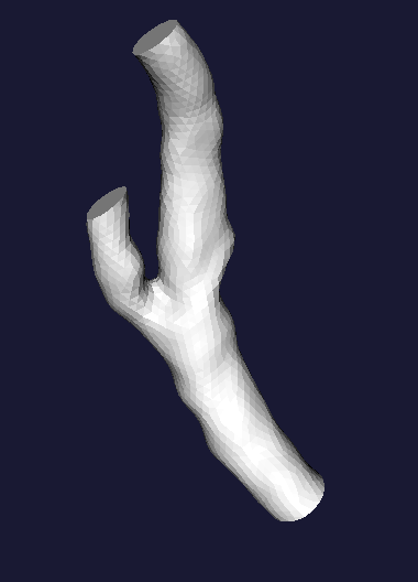
Figure 1: A generic uncapped surface. We will refer to it as foo.vtp
Using vmtkMeshGenerator
Here you can find some examples on how to use vmtkmeshgenerator. All of the meshes displayed below have been generated from the surface in Figure 1, referred as foo.vtp.
Generating a uniform element mesh
It is advisable to adopt this method on branches with uniform dimensions.
vmtkmeshgenerator -ifile foo.vtp -ofile foo.vtu -edgelength 0.5
Where -edgelength is the absolute nominal length of a surface triangle edge.
 |
 |
| Figure 2: Uniform element mesh - Edgelength 0.1 mm | Figure 3: Internal wireframe |
Generating a radius-adaptive element mesh
vmtksurfacereader -ifile foo.vtp --pipe vmtkcenterlines -endpoints 1 -seedselector openprofiles --pipe vmtkdistancetocenterlines -useradius 1 --pipe vmtkmeshgenerator -elementsizemode edgelengtharray -edgelengtharray DistanceToCenterlines -edgelengthfactor 0.3 -ofile foo.vtu
 |
 |
| Figure 4: Distance to centerlines (mm) | Figure 5: Radius Adaptive element mesh - Edgelength Factor 0.3 |
 |
|
| Figure 6: Internal wireframe |
Adding a boundary layer
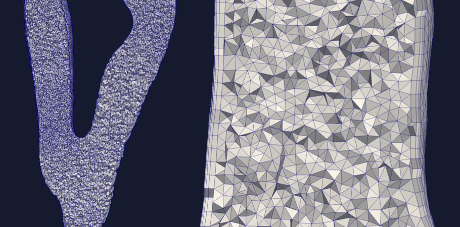
Adding a boundary layer means increasing the element density close to the wall. This is advisable, for example, when dealing with hemodynamics because the solution near the wall is rather important as it’s related to the wall shear stress. To add a layer simply add -boundarylayer 1 to the generator options. To control the layer thickness use the -thicknessfactor parameter. Remember that a boundary layer is made of prismatic elements which are not always recongnized by solvers. In some cases you will have to tetrahedralize your mesh.
vmtksurfacereader -ifile foo.vtp --pipe vmtkcenterlines -endpoints 1 -seedselector openprofiles --pipe vmtkdistancetocenterlines -useradius 1 --pipe vmtkmeshgenerator -elementsizemode edgelengtharray -edgelengtharray DistanceToCenterlines -edgelengthfactor 0.3 -boundarylayer 1 -ofile foo.vtu
 |
 |
| Figure 7: Radius Adaptive Element mesh - Edge Length Factor 0.3 | Figure 8: Radius Adaptive Element mesh - Edge Length Factor 0.3 with Boundary Layer |
Customizing the boundary layer
by Simone Manini, Eng, Orobix Srl, Italy
There is the possibility to fully customize number and dimension of sublayers while generating a boundary layer during mesh generation.
use -sublayers parameter in order to choose how many sublayer will be created and -sublayerratio parameter to set the ratio between one layer and its neighbour. For example:
vmtksurfacereader -ifile foo.vtp --pipe vmtkcenterlines -endpoints 1 -seedselector openprofiles --pipe vmtkdistancetocenterlines -useradius 1 --pipe vmtkmeshgenerator -elementsizemode edgelengtharray -edgelengtharray DistanceToCenterlines -edgelengthfactor 0.3 -boundarylayer 1 -thicknessfactor 0.3 -sublayers 4 -sublayerratio 0.3 -boundarylayeroncaps 0 -ofile foo.vtu

Figure 9: vmtkmeshgeneration with boundary layers
Converting mesh elements to quadratic
vmtklineartoquadratic -ifile foo.vtu -ofile foo_q.vtu -rfile foo.vtp -entityidsarray CellEntityIds
 |
 |
| Figure 10: Linear | Figure 11: Quadratic |
Scaling the mesh
Medical images are often in mm. Typically you want your computations and results to be either in cgs or SI systems, which means scaling the model in cm (1e-1) or in m (1e-3). Let’s scale our mesh in cm and store it in the usual vtu format.
vmtkmeshscaling -ifile foo.vtu -scale 0.1 -ofile foo_scaled.vtu
Inspecting the mesh entities
vmtkmeshboundaryinspector -ifile foo.vtu -entityidsarray CellEntityIds

Figure 12: vmtkmeshboundaryinspector
Tetrahedralizing the mesh
If you added a boundary layer to your mesh you will have prismatic elements in it. Those elements are not always recognized by solvers. In those cases you’ll simply need to tetrahedralize your mesh.
vmtkmeshtetrahedralize -ifile foo.vtu -ofile foo_t.vtu
Linearizing the mesh
This allows you to linearize your mesh preserving its elements.
vmtkmeshlinearize -ifile foo.vtu -ofile foo_l.vtu
Exporting the mesh for your solver
vmtkmeshwriter -ifile foo.vtu -entityidsarray CellEntityIds -ofile foo.msh
Dolfin :
vmtkmeshwriter -ifile foo.vtu -entityidsarray CellEntityIds -ofile foo.xml
libMesh :
vmtkmeshwriter -ifile foo.vtu -entityidsarray CellEntityIds -ofile foo.xda
lifeV :
vmtkmeshwriter -ifile foo.vtu -entityidsarray CellEntityIds -ofile foo.lifev


